
Fleximate® Transport Line: Carts
Carts
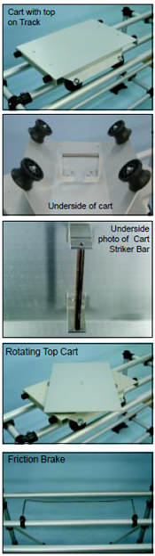
Our one piece cart is constructed of 3/16” aluminum for maximum strength and minimum weight. Its design eliminates the possibility of wheels coming out of alignment. The finish is brushed aluminum with a clear coat anodize. Carts come in 2 widths - 12” and 18” - and can be specified with or without a top. Our stock tops are .125” thick aluminum. The cart wheels are molded polypropylene, each wheel rides on 2 ball bearings.
Electro Static Dissipative Carts (ESD)
All carts are available in an ESD version. The frame and optional top are anodized black.
| Type | Modal No. | ESD Version |
|---|---|---|
| 12" Width with plate top | 80026 | 85026 |
| 18" Width with plate top | 80027 | 85027 |
| 12" Width without plate top | 80028 | 85028 |
| 18" Width without plate top | 80029 | 85029 |
Top Sizes
The 12” top has a surface area of 12” (305 mm) wide x 18” (457 mm) long and 18” wide x 22” (559 mm) long. The short ends have a 1 1/8” (29 mm) return with bumpers mounted on the ends for product and worker safety. Tops are fastened to the cart with four counter sunk machine screws.
Weight Capacity
Our carts are rated for up to 150 pounds (68 kg) so they can be used with either our standard or heavy duty transport line.
Striker Bar
If you plan on using a cart lift system, a lock and go, stopper cylinder or a cart drive system please add the striker bar p/n 90083 on each of your carts.
Rotating Cart Top
The rotating top mounts on a standard size cart frame and is used to facilitate assembly on 4 planes of a product. The top rides on 8 nylon captive ball bearing sockets and an oiled bronze center bearing. The 3/16” (4176 mm) aluminum plate top is locked in 90° quadrants by a spring loaded pin. The 12” cart is 12” (305 mm) x 18” (457 mm) and the 18” cart is 18” (457 mm) x 22” (559 mm).
Model No. 80026RT (305 mm)
Model No. 80029RT (559 mm)
Fleximate® Transport Line: Cart Retention Systems
Cart Retention Systems
For application where side force may be applied to the cart during the assembly process or where exact positioning of the cart is a necessity, Worksmart Systems has developed 2 locking devices: the Lock and Go and the pneumatic Cart Lock. Both options are constructed from delrin for low friction and long wear. Locking or positioning of the cart is accomplished with springs and air cylinders. The Lock and Go and the Cart Stop mounts to a Fleximate transport workstation with universal fittings. A striker bar on the underside of the cart body is used to interface with the Lock and Go and the Cart Stop.
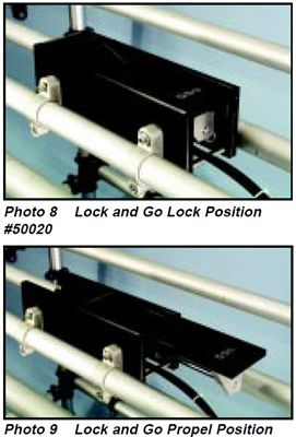
Lock and Go
The Lock and Go (See photo 8 & 9) option performs two functions. First it will retain a cart in position within +-.120. This is accomplished by the striker bar on the underside of the cart riding up and over spring loaded jaws (See photo 8). At this point the cart’s striker bar is retained between the jaws by spring pressure on the underside of the jaws. The second function that the Lock and Go performs is that it will propel the cart as it is released from the jaws. It does this with an air cylinder in a horizontal position that both pushes off and pulls down the forward jaw (See Photo 9). The speed at which the cart is pushed can be adjusted with flow control mounted on the cylinder. The cylinder is actuated by a foot switch but hand controls are available. It will operate between 30 - 120 PSI and all fittings are included. The Lock and Go is suitable for pushing carts over unmanned sections of track, to stop a cart ahead of a gate or for timed pacing of a cell.
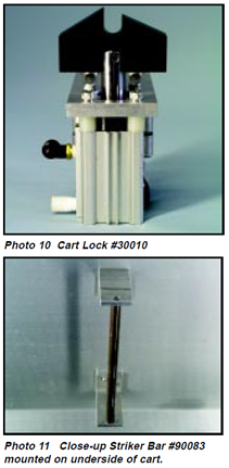
Cart Lock
A more simple approach to cart positioning is our spring loaded cart stop ( See photo #10). This device is mounted between the tracks on FlexiMate transport line. The air cylinder is spring loaded in the extended position. The stopper is machined from a delrin block. As the cart rolls into a station, the striker bar mounted underneath the cart body rides up the stopper until it engages. The cart is then held in position to within +-.020”. To disengage the cart, a foot pedal switch is actuated. Other release methods are available. The cart lock is designed to operate between 30 and 120 PSI.
The spring loaded cart stop can be used to stop and locate the cart for integrated functions such as pressing, driving, and torque applying operations. It also can be interfaced with automated equipment by using reed switches to sense the location of the cylinder motion. It is provided with all fittings and tubing.
Fleximate® Transport Line: Cart Drive System
Cart Drive Systems
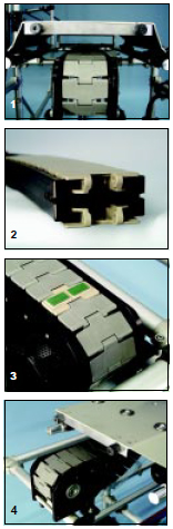
In some cells a means of driving the cart on a Fleximate® transport line may be required. Applications include a paced line, a long return track, or a return track in a “U” shaped cell. For these requirements Worksmart Systems has developed a modular belt drive system the Flexi-Flow which bolts onto the FlexiMate Transport Line workstations and track sections. Motive power is a fractional horse power 120VAC reduction gear motor with a variable speed drive. Power from the belt is transferred to the carts via a striker bar assembly which is fastened to the underside of the cart body (See photo 1). Proximity switches, photo sensors, E-stops, signal lights, and other controls can be provided to your specifications. Both systems are inherently safe, as a cart can be disengaged by lifting one end up to break contact between the cart striker bar and the belt. Every effort has been made to keep the system as simple, inexpensive and maintenance free as possible.
Flexi-Flow
Our Flexi-Flow system consists of a flexible link belt. The belt is flexible in 4 planes: up, down, left and right. The belt is a continuous loop and is guided in a Flexi-Flow channel for both forward and return (See photo 2). Power is transferred from the belt to the cart striker bar (See photo 1) via drive pads which are ultrasonically welded to the links of the belt. (See photo 3). The frequency of spacing of carts on the line can be changed by the placement of the pads. Combining this feature with a variable speed drive gives infinite variations for production pacing. The ultrasonically welded pads are designed for long life and maximum tractive force. In test conditions an 18” cart was able to move 175 pounds before breaking contact with the pads. The drive end and dead end (Photos 3 & 4) utilize a simple cog which meshes with the underside of the belt and are guarded for safety. Belt dimensions are 3.5” wide and 1.5” long per link.
Application
Because of the belts capability to bend sideways this drive system is ideal for applications where the cell layouts include 90° or 180° curves. It can also be utilized for oval or closed loop layouts for a continuous flow.